Royal Festival Hall, London
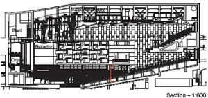
The Royal Festival Hall was the centre piece of the 1951 Festival of Britain on London’s South Bank. Its acoustics have always suffered from ‘ dryness ’ due to an excess of absorbent surfaces and performers found it difficult to hear themselves on stage because the hall is designed to project as much sound as possible away from the stage to reach the back of the vast 3000 seat space.
In a controversial refurbishment quite a bit of the interior has been altered. The walls around the stage have been re-angled and the plywood canopy removed to project less sound away from the stage. Almost all the surfaces have been altered to decrease their acoustic absorbency and increase the reverberation time.
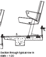
Legroom in the stalls has been increased by 80 mm involving replacing the precast concrete step units that form the raked floor. The new units span between existing saw-tooth concrete beams, modified for the wider steps by breaking out or building up mass concrete on top of the beams. The existing carpet has been replaced with reclaimed teak strip flooring with vents in the risers for a displacement ventilation system.
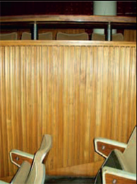
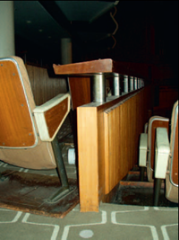
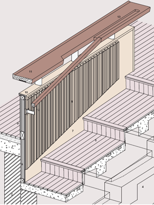
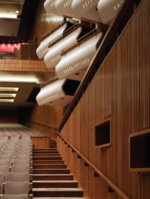
The walls at the sides of the stalls, known as the Copenhagen walls are clad in knuckle-profiled elm strips, originally used in Copenhagen’s Radiohusets Concert Hall to diffuse sound. They originally had gaps between them and were mounted on a hollow studwork wall which distorted the sound. All the timber was stripped off and the existing studwork infilled with dense plasterboard. New timber profiles were made with walnut infill strips between to seal the gaps whilst maintaining a dark shadow-like appearance.
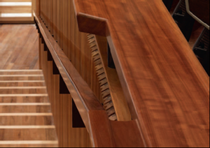
Seats were moved to make new aisles adjacent to the Copenhagen walls with new mahogany handrails that have bronze brackets with a nickel additive to give a silver finish matching the existing handrail brackets. Where the handrail meets the existing balustrade handrail at the top of the stalls the existing mahogany handrail has been cut away and re-shaped to integrate with the new rail.
According to critics the refurbishment has dramatically improved the clarity and vibrancy of the sound.
Drawing labels:
1. Side annexe floor
Existing 160 mm reinforced concrete slab retained. Existing 60 mm foamed slag screed retained. Existing carpet and felt underlay removed. 65 x 15 mm tongued and grooved teak parquet floorboards adhesive bonded to existing screed.
2. Side annexe support wall
Existing 230 mm brick walls supporting concrete slab and precast floors.
3. Raked floor to stalls
840 mm deep precast concrete step units with 200 x 200 mm integral beam spanning from masonry wall at perimeter onto existing concrete saw-tooth beams. Integral beam stopped 140 mm short of end of precast unit so that fl at underside of unit bears on saw-tooth beam. Precast units bedded on 50 mm grout with 20 mm tolerance between adjacent units.
4. Floor sub-structure
Existing 230 mm wide reinforced concrete saw-tooth beams cut back as necessary to support new precast step units. New mass concrete built up on existing beams to increase depth of each step.
5. Floor to steps and stalls
Treads formed from 65 x 15 mm tongued and grooved reclaimed teak parquet strips screwed to timber battens cast into tops of precast concrete step units. 40 x 40 x 4 mm mild steel angle fixed to front edge of precast step unit. 75 x 25 mm reclaimed teak nosing screwed to angle from underside and grooved to take tongued ends of floorboards. Risers formed from 65 x 15 mm tongued and grooved reclaimed teak parquet strips with ventilation slots to plenum beneath floor for displacement ventilation system.
6. Balustrade structure
Existing 50 mm wide softwood carcass fixed to concrete slab and masonry walls retained. All existing timber cladding stripped off. Carcass infilled with 50 mm thick plasterboard to increase density for sound absorption.
7. Lining to stalls
9 mm elm veneered plywood backing screwed and glued to carcass. 9 mm elm veneered plywood skirting, head trim and end panel screwed and glued to backing ply.
8. Timber lining
47 x 32 mm solid elm strips with curved sound-diffusing profile screwed and glued to ply backing. 18 x 18 mm solid walnut strips screwed and glued to ply backing between elm strips to give shadow effect.
9. Lining to side annexe
9 mm elm veneered plywood panel screwed and glued to carcass.
10. Balustrade capping
Existing 95 x 25 mm solid elm capping to top and end of balustrade retained, sanded and resealed.
11. Existing handrail
Existing 305 x 57 mm mahogany handrail retained, sanded and re-sealed. Existing 95 x 10 mm mild steel stiffening plate set into underside of handrail. Existing 50 x 10 mm mild steel vertical support bolted to softwood balustrade carcass. Existing 80 x 45 mm oval profile silvered bronze sheath to vertical supports retained and polished.
12. New aisle handrail
60 x 50 mm mahogany handrail to match edge profile of existing handrail. Silvered bronze fixing brackets with 60 x 30 mm fixing plate screwed to plywood backing on balustrade.
13. Modified existing handrail
1700 mm end section of existing 305 x 57 mm mahogany handrail cut back and new mahogany piece attached to make junction with new handrail to aisle. 50 mm wide 20 mm deep finger groove in top of new handrail section.
Copenhagen wall and handrail detail section at top of stalls
Royal Festival Hall, London
Introduction to Expressed Structural Form
The visual expression of a structure requires an understanding of structural function, and an appreciation of the alternative forms of structure that can perform this function. Broadly, the various forms of steel structure that may be encountered may be grouped as follows:
• Braced frames, in which the beams and columns are designed to resist vertical loads only. Horizontal loads are resisted by bracing in the walls or cores. The connections are designed as pinned or ‘simple’.
• Rigid or ‘sway’ frames, in which the framed structure is designed to resist both vertical and horizontal loads by designing the connections between the members as moment-resisting.•Arch structures, in which forces are transferred to the ground mainly by compression within the structure.
• Tension structures, in which forces are transferred to the ground by tension (or catenary action) and by compression in posts or masts, as in a tent. The tension elements in the form of cables or rods are usually anchored to the ground.
Tension structures are commonly associated with expressive external structures. In practice, many structures are a hybrid of two or more forms. For example, a portal frame acts as a rigid frame in one direction, but is braced in the other direction.
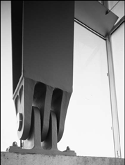
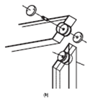
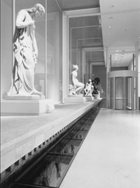
Pinned connections are usually simple to fabricate and are the least expensive type of connection to produce. In pin-jointed frames,lateral stiffness must be introduced into the frame by the careful placement of diagonal bracing, or by incorporating other stabilising methods, such as shear walls, stiff cores, or by interaction with rigid frames. Of course, pin joints do not have to take the form of ‘pins’.Rather, they are simple connections that are treated as pins from the point of view of structural design. Actual pins may be treated ornamentally, as shown in Figure 2.1, and as used at the Sackler Gallery in London (Figure 2.2). Often, connections are designed as‘pinned’, even if they possess some rotational stiffness. The notion of a rigid frame relates to the stiffness of the connections rather than to the rigidity of the frame itself. The achievement of full continuity between members in rigid frames requires an extensive amount of fabrication and, as a consequence, is relatively expensive to achieve. However, rigid frames are suitable for low rise buildings and enclosures, where horizontal forces are low in relation to vertical loads.
 2.1 Pin-jointed connections to column,
sports centre, Buchholz, Switzerland
(architect: Camerzindgrafen Steiner)
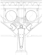
 2.2 Pinned connection between column
and beam at the Sackler Gallery,London:
(a) column–beam arrangement; and
(b) local detail (architect: Foster and Partners)
Given the overall geometry of any one particular structural arrangement, there are many different types of connection which can be made between the members. However, the selection of the structural members, both in their own cross-section and in their connection to other members, must be known before any structural analysis is carried out. There is therefore a close inter-relationship between the architectural requirements for choice of the frame members and their detailed structural design.Often, rigidly framed structures are preferred if there is little opportunity for the use of vertical bracing, such as in fully glazed façades or in large-span structures.
Arch and tension structures rely on the compressive and tensile properties of steel, and follow well-defined structural principles (see Section 2.2 and 2.3).
2.1 Expression of bracing
Of the several methods used to achieve lateral stability in framed construction, diagonal bracing is the one which offers the clearest and most direct visual and graphic representation. For this reason,bracing has been used as an explicit form of structural expression.When brought to the exterior, bracing is often used to ornament the building as well as to serve a structural function. Bracing used for compositional effect can be more than the minimum necessary for structural purposes, as is the case in Figure 2.3.
Figure 2.4 shows a new visitor centre for a thirteenth-century castle, which was built over some of the archaeological relics. The structure had to be lightweight to reduce the size of the foundations,and the number of columns had to be limited to avoid interference with the exhibition space below. The inherently lightweight nature of the building is expressed by an external structure, with the diagonal bracing adding a further element of interest.
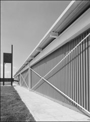 2.3 Reliance Controls, Swindon, with multiple
braced panels (the stubs of the steel roof beams
were left exposed to facilitate easy extensions
to the factory) (architect: Foster and Partners)
2.4 Visitor centre, Limerick, Ireland. The structure of the building is expressed on
the outside, including the vertical bracing (architect: Murray O’Laoire Associates)
2.2 Arched and Curved Structures
Arches are convex structures that are designed primarily to resist compression, as a result of their shape and the form of loading acting on them. Arches are theoretically of parabolic form when subject to uniform loading, but they can be circular, or even made from multiple linear elements. Arches also resist bending moments which are also induced due to non-uniform loading, or the deviation of the arch from the idealised shape in which the lines of thrust (compression) are located within the member cross-section.
Arches in steel may be made of I-sections that are either curved to shape, or made as a facetted arch from multiple straight lengths. They can also be in the form of fabricated members,such as trusses. Arches may have rigid or pinned bases, or a combination of both. Figure 2.5 shows an excellent example of external and internal arches within a multi-storey building used to great structural advantage by spanning over the railway lines at the Broad gate development, London.
 2.5 Internal arch structure over railway lines at Broad gate,
London (architect:Skidmore Owings & Merrill)
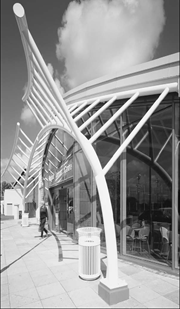
Tubular members are excellent for use in arch construction because of their resistance to buckling and, hence, the few lateral restraints that are required.9At the Windsor Leisure Centre, an arch with variable curvature was continued outside the building envelope,as shown in Figure 2.6.
2.6 Arched roof at Windsor Leisure Centre
(architect : Faulkner Browns)
The roof of the great glasshouse of the National Botanical Garden of Wales used the concept of a curved roof consisting of arches of similar curvature but of reducing span to create a toroidal shape (like a slice through a car tyre), The maximum span of 60 m is achieved with only 324 mm diameter circular hollow sections (CHSs) which support the glass roof.
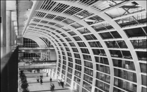
Hong Kong’s new airport uses a variety of novel construction forms, including a long curved canopy over the walkway, as illustrated in Figure 2.7.
2.7 Curved members at Hong Kong International Airport
(architect : Foster and Partners)
Steel members may also be curved in the horizontal plane rather than in the vertical plane, as illustrated in Figure 2.8. In this case, the members are subject to bending and torsion, which is a complex interaction. Inclined curved members can also be used to great effect but, in this case, additional horizontal or torsional support is required to counterbalance the forces. The Merchant’s bridge in Manchester utilises this principle.
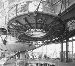 2.8 Curved canopy at the Strasbourg Parliament
(architect:Richard Rogers Partnership)
2.3 Tension structures
In tension structures, ‘ties’ are designed to resist only tension and are crucial elements in the overall structural concept. Tall compression members or ‘masts’ provide for the necessary vertical support, and these masts are located fully or partially outside the enclosure. Cable-stayed roofs, suspended structures, cable nets and membrane structures are all types of tension structures. Good examples of this form of construction are shown in Figures 2.9 and 2.10.
Tension structures can have clear advantages for the roofs of long-span structures or enclosures where the internal function of the space is crucial. In smaller-scale applications, their use is more likely to depend upon a combination of technical and architectural arguments,such as the desire for a lightweight or membrane roof, or to support a glass wall with the minimum of obstruction.
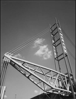 2.9 Home base, London, showing a central
spine supported by tension rods from mast
(architect : Nicholas Grimshaw & Partners)
The tension structure may be partially or fully exposed, and both appearance and function are equally important to detailing.Common examples of structures where tension elements act as primary members include :
• roofs for sports buildings, halls and auditoria
• grandstands
• canopies
• cable-stayed bridges and walkways
• some ‘high profile’ buildings and structures
• railway, airport and other buildings for transportation
• tall glazed walls.
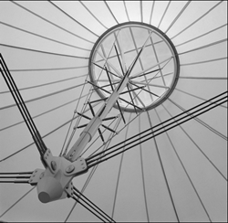 2.10 Tension-supported membrane roof to a central
amenity building, UK side of the Channel
Tunnel (architects: BDP)
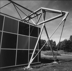
At a modest scale, the tapered columns and cantilevered arms of the roof structure at Stockley Park, London, are supported by horizontal ties, which also enhance the visual effect, as in Figure 2.11.
2.11 Tied column used for architectural effect
at Stockley Park, London (architect:Foster and Partners)
The details employed in tension structures are covered in next Chapter. Tension forces are resisted externally by concrete foundations or by tension piles. The economic design of these components is also important to the overall concept.
2.4 Fabricated members
Fabricated steel sections can be made of a variety of components :
• steel plates to create I-beams, or tapered beams
• I-beams cut into Tee sections
• tubular sections with welded fins.
The following figures illustrate the wide range of architectural effects that can be created by fabricated sections, often at large scale.
The Financial Times building in Docklands, London, used half tubes, welded plates and projecting fins to create wing-shaped columns that are external to the fully glazed envelope. The overall effect is illustrated in Figure 2.12, and the cross-section of the column is shown in Figure 2.13.
2.12 Financial Times building, London
(architect : Nicholas Grimshaw & Partners)
2.13 Details of column in Figure 2.12,
Financial Times building, London
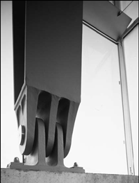
The curved beams at Stratford Station, London, were welded from plate and stiffened at points of high curvature, as illustrated in Figure 2.14. Interestingly, cast steel footings connected the curved beams to the concrete ground beam, and accentuated the local curvature.
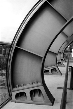 2.14 Curved fabricated beam at Stratford
Station, London (architect: Wilkinson Eyre)
The enclosure of BCE Place in Toronto, based on a concept of Santiago Calatarva, used tapered columns comprising four fins that reduce to a fine arch over the enclosure between adjacent buildings.
The Cranfield Library used a welded V-shaped spine-beam to support the curved roof, as illustrated in Figure 2.15 and in the detail in Figure 2.16.
2.15 Fabricated V beam of Cranfield Library
(architect: Foster and Partners)
2.16 Detail of a fabricated section
used at Cranfield Library
2.5 Structure / Envelope Relationship
Steel is often used in applications in which the relationship with the building envelope is important to the visual effect. There are five basic relationships between the enclosure of a building and the primary structure :
• structure located entirely inside the building envelope
• structure located in the plane of the building envelope
• internal structure continued outside the building envelope
• semi-independent external structure supporting external wall,glazing or roof
• structure located completely outside the building envelope (Figure 2.17).
At Bed font Lakes, London, the beams and columns were located in the plane of the building envelope and used expressed connections. Many ‘tent-type’ structures continue to support the structure through the building envelope, as was done at the Dynamic Earth Centre, Edinburgh, illustrated in Figure 1.5. The same concept was also used in the glazed cladding support to the Western Morning News building, Plymouth. An early example of a completely external structure is the Inmos factory in Newport, south Wales, shown in Figure 2.17.
2.17 Structure outside the building envelope, Inmos, Newport
(architect : Richard Rogers Partnership)
This relationship between the envelope and the primary structure brings with it other issues important to the building design, such as :
• expression of the connections
• foundation and holding down points
• security and access (for external structures)
• fire-safety strategy
• corrosion protection of the external elements
• ‘cold-bridging’ through the envelope
• secondary supports to the roofs and walls to complement the chosen structural solution.
The mixture of structural elements, including curved members,trusses, fabricated components, cables, cast and stainless steel elements, illustrates the variety of techniques that are achievable.
The repetition of the internal structure externally can also be used to great visual effect. The curved frame of Stratford Station in Figure 2.18 was extended outside the glazed façade to emphasise the structural solution. The tapered fabricated beams were curved with decreasing radius down to heavy cast steel footings. This same notion was first used in the Centre Pompidou, Paris, where the external framework replicates the internal structure.
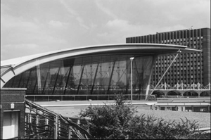 2.18 Stratford Station showing use of repetitive
curved frames (architect : Wilkinson Eyre)
Buildings can be extended later by using the external frame work to connect into the structure of the extended building without having to remove the existing cladding. This is important in the operation of existing buildings, which would otherwise lead to disruption of internal activities.

